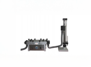
Measures the in-plane water flow rate (transmissivity) of plastic drainage boards.
WhatsApp : +86 15601902607
Email : info@qinsun-lab.com

The geotextile permeability tester is a testing device designed and developed using the JIGAOTEST system, used to measure the water permeability of geosynthetic materials and related composite materials in the vertical direction.
It is used to measure the characteristics of the plastic drainage plate in the plane direction of the water flow under the specified pressure. During the test, seepage was carried out under the condition that the lateral pressure of the sample was 350kPa and the hydraulic gradient i=0.5. and the water seepage of the sample in a certain period of time was measured.
JTG E50 T1143-2006: Test Methods of Geosynthetics for Highway Engineering
SL/T235-26-2012: Testing Specification of Geosynthetics for Water Conservancy Projects
JT/T 521- Appendix A-2004: Geosynthetics in Highway Engineering - Plastic Drain Board (Strip)
JTS-206-1- Appendix B B.3-2009: Technical Specification for Application of Geosynthetics in Port and Waterway Engineering
JTS/T245-2023: Testing Specification of Geosynthetics for Port and Waterway Engineering
Customized pressure gauge with imported high precision diffused silicon pressure sensor and 16-bit high resolution A/D converter;
High energy lithium sub-battery is used to power the pressure gauge, and the continuous use time is more than 1.5 years;
Pressure gauge can be adjusted to zero with one click, suitable for a variety of environments;
"kPa, MPa, Psi, mmHg, Bar, Kgf/cm2" six units can be switched;
The open-type hatch door structure is convenient for sample loading.
The body adopts the casting aluminum integrated molding process to ensure the sealing of the pressure chamber;
The specially designed sample holding device prevents the deformation of the plastic core plate of the drainage plate, combined with the sealing design, to ensure that the sample holding is air-tight and water-tight;
The hydraulic gradient can be adjusted by the height of the water tower.
Reasonable design of waterway pipeline reduces the loss of water head in the test, and the result is more accurate;
Pneumatic control element to control the inlet and outlet of compressed air and the size of pressure, to provide side pressure for the test;
Pressure chamber and seal plate can be customized according to customer requirements to meet different sizes of samples.
| Description | Details |
|---|---|
| Test chamber structure | Open |
| Effective length of the sample | 400mm |
| Sample width | 100mm (can be customized) |
| Side pressure | 350 + 20kPa (gauge accuracy 0.4%FS) |
| Head difference adjustment range | 0 - 400mm |
| Accuracy | 0.4% |
| Dimensions - Host | 715x300x260mm |
| Dimensions - Water tower | 440x440x860mm |
| Weight | 35kg |
Clamping device
Water level measuring cylinder
Time controller
Thermometer
Base and container
Control piping system
Power supply and control circuit
1. Sample clamping: Remove the clamp 21. loosen the tightening nut 20. place the sample flat on the lower clamp surface, press the upper clamp onto it, then tighten the tightening nut 20. and place the clamp on the positioning support pin 19.
2. Turn on the power switch 10. and set the collection time value on the time counter 9 (the range of the time counter 9 of this instrument is 0-99.99 seconds; according to GB/T15789-1995. the set time should be >10 seconds).
3. Ensure that the drain port 18 is closed, and after connecting a stabilized water source to the inlet 16. open the flow control switch 5. and direct the outlet nozzle 2 towards the water level measuring cylinder 4 to fill the instrument with water until the water level exceeds the sample surface and reaches the height of the inner container 6. At this time, the water head pressure difference is zero.
4. After the water level stabilizes, continue adding water. Water will begin to overflow from the inner container. Adjust the flow control switch 5 to control the water flow to obtain a fixed pressure difference, i.e., the water level in the measuring cylinder 4 is stable. At this time, the overflowing water is discharged through the drain port 17.
5. After the water head pressure difference stabilizes for 30 seconds, press the [Work] button 8. The time counter 9 starts timing, and the solenoid valve switches the outlet. At this time, the overflowing water flows out through the sampling port 11. Collect the outflowing water in a container, and then measure the specific value with a measuring cylinder, up to 10 mL (the collected water volume should be >1L; if it is less than 1L, the time setting value should be increased accordingly); after the set time is reached, the solenoid valve operates, and the overflowing water is discharged from the drain port 17.
6. While performing the above steps, read the temperature value on the thermometer 3. The water temperature should be between 10 and 25℃ (to 0.1℃).
7. Repeat steps 6.3 to 6.6. A total of 5 sets of readings are obtained, with water flow velocities evenly distributed between 0 mm/s and 60 mm/s. During the test, the water flow velocity is tested from high to low. 8. Repeat steps 6.2 to 6.7 to test the remaining samples under the same water pressure.
9. Turn off the power switch 9 and unplug the power cord 14.
10. Open the drain valve 18 to drain the remaining water from the instrument.
11. Process the test data according to GB/T15789-2005.
Qinsun Instruments Co., LTD is a professional laboratory testing instrument manufacturer in China,Have been focusing on laboratory instrument R&D more than 30 years and have rich industry experience,Based on international testing standards,We are also the instrument supplier for BV SGS laboratory,We provide one-stop solutions for lab instruments,Free Training and Turn-Key Service,Products exported all over the world,Offer 36 month warranty and are a trustworthy partner.

Company Phone
+86-21-6420 0566
Working hours
Monday to Friday
Mobile phone:
13816217984
Email:
info@qinsun-lab.com