Time: Popularity:0times
In the fields of materials science, engineering testing, and quality control, the electronic universal testing machine (UTM) has become an indispensable core piece of equipment due to its high precision and versatility. It can accurately simulate various complex mechanical environments, from static to dynamic, performing a series of mechanical property tests on metals, polymer composites, building materials, textiles, etc., including tensile, compression, bending, shear, peel, and fatigue tests, thereby evaluating key parameters such as strength, toughness, elastic modulus, and Poisson's ratio.
However, like all high-end instruments integrating precision mechanics, advanced sensors, and complex control software, electronic universal testing machines inevitably experience various malfunctions due to factors such as operation, environment, and aging during long-term, high-frequency use. If these malfunctions are not diagnosed and eliminated in a timely and accurate manner, they will not only affect the accuracy of research data and the reliability of production quality control, but may also shorten the service life of the equipment. This article systematically analyzes common fault types of electronic universal testing machines, provides a set of effective troubleshooting procedures and diagnostic techniques, and supplements them with detailed daily maintenance strategies. The aim is to build a complete knowledge system for users, from theory to practice, to help improve equipment efficiency and stability.
Fault Phenomenon: During testing, the force value display is unstable, fluctuates violently, or shows a systematic deviation from the nominal value of a known standard sample/weight.
Sensor Problems: The force sensor itself suffers from decreased sensitivity, zero-point drift, or damage to the internal strain gauge due to overload, impact, or aging.
Signal Transmission Interference: Poor contact in the signal line from the sensor to the amplifier, damaged shielding layer, or electromagnetic interference from surrounding high-power equipment (such as frequency converters, motors).
Calibration Failure: Failure to perform calibration according to the prescribed cycle, or improper operation during the last calibration, resulting in incorrect calibration coefficients.
Mechanical misalignment: Improper sample installation or misalignment of the clamps leads to lateral forces, affecting the accuracy of unidirectional measurements by the sensor.
Connection and environmental checks: First, ensure all signal connectors are secure, check for damaged signal cables, and keep the testing machine away from strong electromagnetic interference sources.
System calibration: Use a higher-grade standard force gauge or standard weights, and strictly follow national standards or the equipment manual for full-range calibration (including zero point, full scale, and multi-point linearity). If the problem persists after calibration, the sensor itself is highly likely faulty.
Replacement verification: If possible, use a known good sensor of the same model for testing; this is the most direct method to determine the sensor's condition.
Fault symptoms: The beam cannot start, its movement speed is unstable, there are abnormal noises, or it suddenly stops during operation.
Drive system failure: The servo motor or stepper motor itself is damaged, or its driver is triggering an alarm (such as overcurrent or overload).
Transmission Mechanism Issues: Ball screws and guide rails may become worn or corroded due to lack of lubrication from prolonged use, or foreign objects may cause them to seize.
Control System Command Errors: Abnormal output from the motion controller or incorrect software parameter settings (e.g., speed or acceleration settings are too high).
Safety Limit Trigger: Improperly positioned, accidentally triggered, or damaged mechanical or photoelectric limit switches cause the system to stop operating for safety protection.
Basic Checks: Confirm the emergency stop button is reset and the power supply voltage is stable.
Observation and Diagnosis: Manually attempt to slowly move the crossbeam, feeling for any jamming points, and listen for any abnormal friction sounds from the motor and lead screw.
Cleaning and Lubrication: Regularly (e.g., every 2000 hours of operation) thoroughly clean the lead screw and guide rails and apply the manufacturer-specified grease.
Limit Check: Manually trigger each limit switch, observe the software prompts for accuracy, and adjust their positions to the appropriate range.
Data Acquisition and Software System Failures: Data Loss, Communication Interruption, or Software Crash
Fault Symptoms: The computer cannot receive data, the software interface freezes or displays errors, or test data cannot be saved.
Hardware Connection Interruption: Loose or oxidized USB, Ethernet, or PCIe data acquisition card connection cables.
Software Conflicts and System Issues: Operating system updates causing incompatibility with the testing machine software; computer virus infection; running multiple resource-intensive programs simultaneously.
Driver Abnormalities: Incorrectly installed or outdated acquisition card or controller drivers.
Software Defects: Undiscovered bugs in the program, or errors triggered under specific operation sequences.
Restart and Reconnect: Close the software, restart the computer, and reconnect all communication cables.
System Environment Cleanup: Ensure the "cleanliness" of the dedicated test computer; do not install irrelevant software; perform regular virus scans and system optimization.
Driver and Updates: Visit the equipment manufacturer's website to download and install the latest drivers and software patches.
Log Analysis: Review the software runtime logs or system event viewer to find detailed error codes, providing crucial information for technical support.
Symptoms: The specimen slips within the jaws, or fracture always occurs outside the gauge length (e.g., near the fixture end).
Improper Fixture Selection: Using flat-jaw fixtures to hold smooth plastic specimens, or using V-shaped fixtures to hold sheet metal.
Poor Clamping Force Control: Insufficient pressure from pneumatic or hydraulic fixtures, or manual fixtures not tightened properly; conversely, excessive clamping force can prematurely damage or crush the specimen.
Specimen Misalignment: The specimen is misaligned between the upper and lower fixtures, resulting in uneven stress and additional bending stress.
Correct Fixture Selection: Select appropriate specialized fixtures (e.g., wedge-shaped, winding, or flat-push pneumatic fixtures) based on the specimen material and shape (e.g., wire, sheet, film, elastomer). Standard Operation: Ensure the clamping surfaces are clean and free of foreign objects. For brittle or high-strength materials, a suitable shim can be placed between the jaws and the specimen. Strictly follow the standard method to install the specimen, ensuring its axis coincides with the tensile centerline.
Controlling Clamping Force: For equipment with adjustable clamping force, find the optimal pressure value through pre-experimentation that prevents slippage without damaging the specimen.
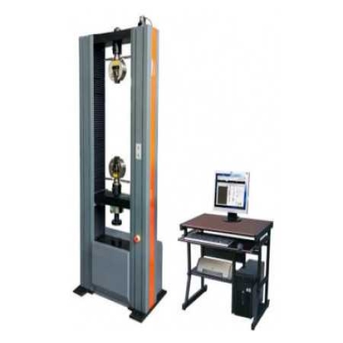
10kN Universal Testing Machine
When a fault is found in the electronic universal testing machine, first, record the fault phenomena in detail, including the time of occurrence, operating process, abnormal sounds, and error messages displayed on the screen (if any). Then, based on the fault phenomena, conduct a preliminary analysis of possible causes. This requires a certain understanding of the testing machine's structure, working principle, and common fault types.
Unstable power supply or poor connections are common causes of many electronic equipment faults. Check whether the testing machine's power cord is firmly plugged in, whether the voltage is stable, and whether the connections between components are loose or damaged. Also, confirm that the power socket is properly grounded to prevent electrostatic interference.
Troubleshooting Hardware Faults:
Sensor Inspection: Sensors are crucial for data acquisition in the testing machine. Check for damage, wiring blockages, and signal stability.
Motor and Transmission System: Check motor operation for abnormal noises or overheating. Inspect transmission systems such as belts and gears for wear or looseness.
Control System: Including controllers and circuit boards, check for burn marks, missing components, or poor contact.
Software and Program: Confirm the software version is up-to-date and check for known software defects. Verify program settings, such as test parameters and control logic, are correct.
Replacement Testing Method: For suspected faulty components, the replacement method can be used. Replace the suspected faulty component with a known working one and observe if the fault disappears, thus pinpointing the problem.
Fault Diagnosis Techniques:
Utilizing Diagnostic Programs:Modern electronic universal testing machines are typically equipped with fault diagnosis programs that automatically detect and report system faults. Users should familiarize themselves with these programs for quick problem location.
Utilizing Diagnostic Programs:
Observation and Listening:Carefully observe the testing machine's operation, noting any abnormal vibrations, oil leaks, or air leaks. Simultaneously, listen to the sounds the equipment makes during operation; abnormal sounds often reveal mechanical or electrical faults.
Based on the testing machine's working principle and fault symptoms, conduct logical analysis to deduce possible causes of the fault. For example, if the testing machine suddenly stops during loading and displays an overload error, it may be due to abnormal sensor signals, triggered control system protection mechanisms, or a malfunction in the loading mechanism.
Regularly clean the testing machine to remove dust, oil, and other impurities, keeping the equipment's surface and interior clean. Lubricate sliding parts and transmission mechanisms to reduce wear and friction.
Regularly inspect and calibrate the testing machine's performance indicators according to the equipment manual to ensure the accuracy and reliability of test data. Key components such as sensors and displacement gauges require regular precision calibration.
Operators should be familiar with the testing machine's operating procedures and operate it according to the prescribed steps and methods. Avoid overloading, frequent start-stop cycles, and other improper operating methods to reduce equipment wear and tear and malfunctions.
Create detailed maintenance records for each testing machine, recording the time, content, replaced parts, and repair results of each maintenance session. This helps track the equipment's maintenance history, promptly identify potential problems, and take remedial measures.
Through systematic fault analysis, scientific maintenance strategies, and a deep understanding of common problems, users can significantly improve the efficiency and data reliability of electronic universal testing machines, allowing this precision equipment to realize its maximum value in scientific research and quality control.

Company Phone
+86-21-6420 0566
Working hours
Monday to Friday
Mobile phone:
13816217984
Email:
info@qinsun-lab.com
