Time: Popularity:0times
In the field of safety, determining the explosion limits of flammable gases or dust is a core aspect of accident prevention. Standard International Group (HK) Limited, a national high-tech enterprise, has independently developed explosion limit testing instruments driven by technological innovation. These instruments integrate high precision, intelligence, and safety, providing scientific and reliable safety assessment tools for industries such as chemical, energy, and fire protection.

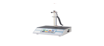
Standard Group's explosion limit detectors utilize the closed-container method, combining a multi-channel gas mixing system with high-precision sensors to accurately determine the lower explosive limit (LEL) and upper explosive limit (UEL) of gases, vapors, and dust. The equipment incorporates thermocouples with ±0.5℃ accuracy and pressure sensors with ±0.1%FS accuracy, ensuring the absolute reliability of temperature and pressure data. The patented gas mixing module supports inert gas dilution and complex environment simulation, adapting to different media testing needs. The measurement error rate is less than 30% of the industry standard, providing authoritative data support for risk assessment.
The equipment integrates an embedded processor and a Windows operating system, achieving fully automated control throughout the entire process. From vacuuming, gas mixing, and ignition to data acquisition, everything can be completed with a single touch on the touchscreen, increasing operational efficiency by over 50% compared to traditional equipment. The AI data analysis module automatically generates explosion limit curves and risk assessment reports, and supports cloud storage and sharing of data, helping enterprises build a digital safety management system.
Standard Group consistently prioritizes experimental safety as a core design principle. The explosion limit detector is equipped with a triple safety protection mechanism: the explosion-proof observation window uses high-strength tempered glass, capable of withstanding a 10kPa explosion impact; the pressure relief device and dual interlock system monitor pressure changes in real time, automatically cutting off the gas supply and initiating pressure relief in case of an anomaly; and a high-definition video monitoring system records the entire explosion process, providing visual evidence for subsequent analysis and ensuring the safety of personnel and equipment.
As an industry benchmark with 22 national patents, Standard Group continuously upgrades the performance of its explosion limit detection instruments. The third-generation equipment adds an intelligent calibration function, automatically correcting for environmental interference factors and improving long-term stability by 40%. Modular design supports functional expansion and is compatible with various experimental modes such as gas explosion, dust explosion, and thermal stability testing, allowing a single unit to meet diverse testing needs.
We not only provide the equipment, but also offer full lifecycle service support. From equipment delivery to after-sales maintenance, Standard Group has a professional team to provide customized solution design, operation training, and regular maintenance services. Core components are guaranteed for 3 years, and 24/7 technical response ensures customer peace of mind.
Choosing Standard Group's explosion limit detector means choosing accuracy, safety, and efficiency. For product details, please contact our technical team to jointly safeguard production safety!

Company Phone
+86-21-6420 0566
Working hours
Monday to Friday
Mobile phone:
13816217984
Email:
info@qinsun-lab.com