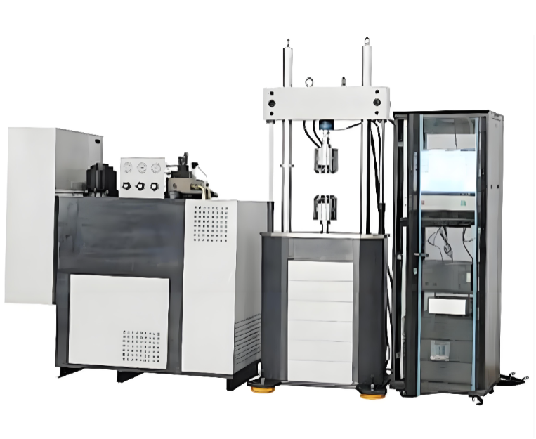
The Automotive Control Arm Durability Test Bench is mainly used to perform durability tests on autom
WhatsApp : +86 15601902607
Email : info@qinsun-lab.com

The Automotive Control Arm Durability Test Bench is mainly used to perform durability tests on automotive control arms, tie rods, and stabilizer bars according to the required testing specifications.
ISO 16750 (Road vehicles — Environmental conditions and testing for electrical and mechanical components)
SAE J2140 (Automotive Suspension Component Durability Testing)
GB/T automotive component durability test standards
OEM-specific durability test specifications for automotive suspension components
Used for durability and fatigue testing of automotive control arms, wishbones, stabilizer bars, and suspension linkage components to evaluate their structural strength, fatigue life, and reliability under simulated road load conditions.
| No. | Item | Specification |
|---|---|---|
| 1 | Linear Servo Actuator Test Force | Vertical: ±10 kN; Horizontal: ±25 kN |
| 2 | Linear Servo Actuator Piston Stroke | Vertical: 250 mm; Horizontal: 200 mm |
| 3 | Linear Servo Actuator Frequency Range | Vertical: 5 Hz; Horizontal: 15 Hz |
| 4 | Linear Servo Actuator Displacement Accuracy | ±0.50% |
| 5 | Linear Servo Actuator Force Accuracy | Within 2% range, ±0.5% at each point |
| 6 | Control System Channels | 2 channels, coordinated control of two channels |
| 7 | Linear Actuator Control Mode | Force control and displacement control with smooth switching |
| 8 | Main Test Waveforms | Sine wave, triangular wave, rectangular wave, ramp wave, etc. |
| 9 | Hydraulic Power Supply | 21 MPa, 120 L/min; 45 kW AC; noise ≤70 dB |
| 10 | High and Low Temperature Environmental Chamber | -40°C to +50°C |
Used for durability testing of various automotive control arms (wishbone arms) and stabilizer bars.
One end of the test specimen (usually the bushing end) is hinged to the base through a fixture. The other end (usually the ball joint end) is connected through fixtures to a vertically arranged actuator and a horizontally arranged actuator, respectively. The vertically mounted actuator drives the control arm to perform up-and-down oscillating movements, while the horizontally mounted actuator applies a horizontal load to the control arm. The two actuators are arranged vertically and horizontally, respectively.
The vertical actuator applies a load of ±10 kN with a stroke of 250 mm.
The horizontal actuator applies a load of ±25 kN with a stroke of 200 mm.
1. Main Frame
Platform-type structure. The test platform is machined to ensure the accuracy of the test reference plane.
The vertical actuator is installed on an inclined cantilever beam, while the horizontal actuator is installed on a horizontal sliding seat. Both the sliding seat and the inclined beam can be adjusted in position on the test platform.
2. Electro-Hydraulic Servo Actuator
Suitable for dynamic and static test applications.
Vertical loading actuator test force: ±10 kN; Horizontal loading actuator test force: ±25 kN.
Double-rod piston structure: Vertical actuator stroke: 250 mm; Horizontal actuator stroke: 200 mm.
The piston and piston rod surfaces are hard chrome plated.
High-speed sealing elements are used between the piston and cylinder body, as well as between the piston rod and end cover. High-speed support rings are adopted to provide support, ensuring high actuator stiffness and strong lateral resistance.
The actuator is equipped with a dynamic displacement sensor, an external electro-hydraulic servo valve, and a force sensor, providing two closed-loop control systems for force and displacement control.
The force sensor is installed at the piston rod head and equipped with a preloaded ring to ensure reliable connection during dynamic testing.
Hydraulic cushioning zones are designed at the actuator amplitude limit positions to prevent damage caused by uncontrolled operation.
3. Sensors and Servo Valve
Proportional Servo Valve: 21 MPa, 60 L/min; directly integrated with the actuator through a servo valve connection block.
Force Sensor: ±30 kN. ±20 kN sensor adopts imported U.S. products, with 150% overload capacity. Combined with the control system, the static accuracy is ±1%; dynamic accuracy is ±3%; phase coordination accuracy is ≤2°.
Displacement Sensor: Magnetostrictive non-contact dynamic type. Effective measuring range (displacement): ±150 mm / ±100 mm. Combined with the control system, indication error is ±0.5% FS; axial displacement measurement accuracy is 0.001 mm. Sensors are calibrated before delivery.
Qinsun Instruments Co., LTD is a professional laboratory testing instrument manufacturer in China,Have been focusing on laboratory instrument R&D more than 30 years and have rich industry experience,Based on international testing standards,We are also the instrument supplier for BV SGS laboratory,We provide one-stop solutions for lab instruments,Free Training and Turn-Key Service,Products exported all over the world,Offer 36 month warranty and are a trustworthy partner.

Company Phone
+86-21-6420 0566
Working hours
Monday to Friday
Mobile phone:
13816217984
Email:
info@qinsun-lab.com