BackgroundNumerous test rigs have been devised for investigating valve seat recession, ranging
WhatsApp : +86 15601902607
Email : info@qinsun-lab.com

Numerous test rigs have been devised for investigating valve seat recession, ranging from motored engine and cylinder head rigs to devices based on servo hydraulic actuators.
The rigs based on engines and cylinder heads typically use standard cam shafts for generating the motion. The cam designs are invariably constant acceleration as opposed to constant velocity devices, hence a given velocity is only achieved at a specific valve displacement.
At the frequencies and amplitudes required for a sensible test rig, servo hydraulic actuators will typically be capable of generating only sinusoidal motion, hence, once again, a given velocity is only achieved at a specific displacement.
It is generally agreed that valve seat recession is dependent on the velocity of the valve at impact with the seat. Clearly, the velocity of the valve at any part of the cycle preceding impact is of no relevance. It follows that any device that uses either a constant acceleration type cam or a servo hydraulic actuator to generate the motion, will require very precise adjustment of the relative position of valve and seat in order to achieve the required impact velocity. Furthermore, as wear takes place, the position of impact relative to the motion will change and hence the velocity of impact will change.
The logical conclusion has to be that instead of using a constant acceleration cam the rig should use a constant velocity cam, so that it does not matter where the impact occurs relative to the motion, the velocity will always be the same. With an actuator, logically one should use a saw-tooth as opposed to a sinusoidal motion; this is achievable, but not at anything other than modest frequencies.
A constant velocity cam is of course only possible in theory, as the change of direction at TDC and BDC would necessarily require infinite acceleration.
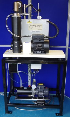
The STD-TE 35 Valve Impact Rig uses cams that are constant velocity over at least sixty degrees of rotation, with profiles designed to give variable velocity either side of TDC and BDC. Impact velocity, which, as with other rigs, varies with rotational speed, is essentially constant over a significant part of the valve motion.
| Maximum Rotational Speed: | 3.000 rpm | |
| Maximum Impact Velocity at 3.000 rpm: | ||
| 4 mm cam: | 600 mm/s | |
| 6 mm cam: | 857 mm/s | |
| Maximum Valve Temperature: | 450°C | |
| Maximum Seat Temperature: | 350°C | |
| Valve Lengths: | ||
| Smallest: | 85 mm | |
| Largest: | 170 mm | |
| Services | ||
| Electricity: | 220/240 V, single phase, 50/60 Hz, 7.5 kW |
Qinsun Instruments Co., LTD is a professional laboratory testing instrument manufacturer in China,Have been focusing on laboratory instrument R&D more than 30 years and have rich industry experience,Based on international testing standards,We are also the instrument supplier for BV SGS laboratory,We provide one-stop solutions for lab instruments,Free Training and Turn-Key Service,Products exported all over the world,Offer 36 month warranty and are a trustworthy partner.

Company Phone
+86-21-6420 0566
Working hours
Monday to Friday
Mobile phone:
13816217984
Email:
info@qinsun-lab.com