Application:Dynamic Footwear Water Resistance Tester is designed to determine the dynamic water resi
Email: info@standard-groups.com
Dynamic Footwear Water Resistance Tester is designed to determine the dynamic water resistance of all types of shoes.
The water tank is filled with a specified volume of colored water. A specimen is put on the artificial foot and flexed at a given angle and speed, and inspected at intervals for water penetration.
Control Mode:PLC Touch screen control
Test Quantity:2 Sets
Flexing Angle:25±2°
Flexing Speed:60±6cpm
Counter:0~999,999
Dimension(W×D×H):85×70×80cm
Weight:Approx 110kg
Power:1∮, AC220V,50/60Hz,3A (Specified by user)
Standard Accessories:Water sensor 2pcs
SATRA TM 230,
ISO20344-2021 section 5.19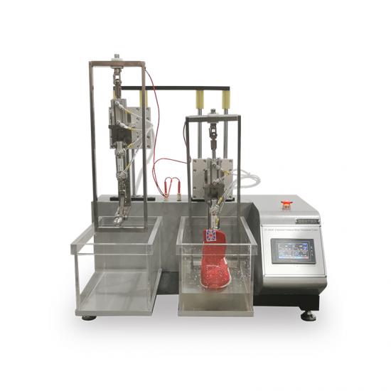
Disclaimer: The above content is for reference and communication only among industry insiders, and does not guarantee its accuracy or completeness. According to relevant laws and regulations and the regulations of this website, units or individuals who purchase related items should obtain valid qualifications and qualification conditions.

Company Phone
+86-21-6420 0566
Working hours
Monday to Friday
Mobile phone:
13816217984
Email:
info@qinsun-lab.com